Note: This is NOT a tutorial. I am putting this document here because I want it to be together with the project's docs and because there's only one way to include my own docs in JSDoc, which is in the tutorial.
Problem #1
If your finger touches your hand, does your hand feel your finger first, or the other way round?
Assuming the following code:
var batt = new Battery(),
    wire = new Wire();

batt.P.to(wire.A); // battery's 'Positive' end connect-to wire's 'A' end
// in the reality, this should have the same effects as "wire.A.to(batt.P)"
In other words, when one end of a wire is placed on top of the battery's end, which one should be "connected" to the other? Which one should change the state of the other, or both?
Solution:
Instead of one end connecting to the other, we have a middle-person to handle the connections - a slot, or position of a grid. Now, the code would look something more like this (assuming there's a grid object that "owns" the coordinates)
var batt = new Battery(),
    wire = new Wire();

batt.P.to(1,1); // to(x,y) - coordinates of a grid or board
wire.A.to(1,1);
If you think about it now, the grid object can then store / manipulate the states for both the components to interact with!
Problem #2
Now that I know how components can 'connect', I still don't know how to put a lot of things together i.e. how are we going to calculate the voltage, conductance, etc? The major obstacle I have for this project is my lack of (or almost negligible) experience and understanding in the field of electrical / electronic. The good thing is that there are tons of resources online such as the conceptual way of how circuit sims work (see Resources Section, too lazy to reference anything at this point).
Solution:
After doing some reading, I realised that there are just a whole lot more than Ohm's Law and Kirchhoff's Law to developing a complete circuit sim. One of the things for me to learn is Nodal Analysis + Gaussian Elimination (to solve the system of linear equations from it). However, Nodal Analysis will not be enough since it's just for DC Analysis only. Either way, this is still a good start for me to take on this project.
Problem #3
"Ground control to Major Tom..."
As I am trying to make Nodal Analysis the one method to rule them all (KCL & KVL) for DC analysis, I have found myself to be in a pickle. One of the steps of Nodal Analysis is to choose a reference node and mark the node voltage to 0, and we can then calculate the other nodes' voltages with reference to it i.e., we have to 'make' a node the ground of the circuit. Which leads to the problem - how should I decide where the ground should be? If a different node is chosen as a ground, wouldn't that give a different result? What would be the criteria for a node to be best suited as the ground?
Solution:
So how am I to decide what is the best / ideal place for a ground? Answer, I don't. As I am not aiming to write a software that provides advice or to decide the best solution for the user, what I can do is to leave that responsibility to the user him/herself. In other words, the user will decide and add the ground 'component' onto the circuit.
Create tools to not show what things should be, but what things can be! Unless it's a code linter.
Main take away: Remind yourself of the reason for doing the project, and what it is for.
Problem #4
While I was practising Nodal Analysis with various simple circuits, I came across a challenge - how do I write the KCL equation for a node with a branch that only has a voltage source i.e. a V-branch? Since the branch does not have (significant) resistance, how am I going to calculate the current in that branch?
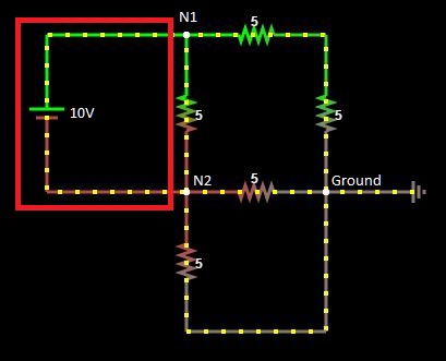
Highlighted in red: V-Branch a.k.a. evil branch as said by L.R.Linares
The easiest way is to place the ground component at the negative end of the source, but remember, for the solution to Problem #3 we are giving the user the freedom to place the ground anywhere.
Assuming the following circuit is what I am trying to solve:
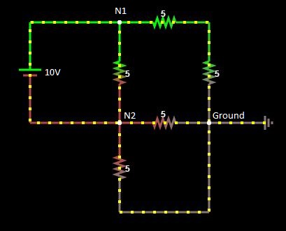
KCL for Node 1:
    -I + (V1-V2)/5 + (V1)/10   = 0
    3V1 - 2V2 - 10I            = 0 // equation #1
KCL for Node 2:
    I + (V2-V1)/5 + 2(V2/5)    = 0
    -V1 + 3V2 + 5I             = 0 // equation #2
So now, I have three variables V1, V2 and I to solve but only 2 equations... sadFace.jpg.
Solution:
Turns out this could be easily solved by introducing a simple equation for the V-branch:
V+ = V- + Vsource
Explanation: Voltage at positive end = Voltage at negative end + Voltage of source
And that's it! What I have now is the equation V1 = V2 + 10V, and I just have to sub that into equations #1 and #2 then we'll be left with only two variables for two equations!
Equation #1
3V1 - 2V2 - 10I         = 0
3(V2 + 10V) - 2V2 - 10I = 0
V2 - 10I                = -30V

Equation #2
-V1 + 3V2 + 5I           = 0
-(V2 + 10V)> + 3V2 + 5I  = 0
2V2 + 5I                 = 10V
After substitution / Gaussian elimination, we get V2 = -2V and I = 2.8A.
With that, we can continue solving for V1 and the rest of the circuit. Big thanks to L.R.Linares' video on Modified Nodal Analysis that provided me with the V-branch equation, the key to solving this problem.
Problem #5
I need to solve a system of linear equations, KCL equations in particular, for Nodal Analysis. Algebra.js seems to be just the maths library I need, since it has algebra.parse to parse string into a simplified expression (go check it out, it's awesome!). Now, the problem is getting the KCL equation for each node - how is that suppose to work?
(Potential) Solution
I haven't come up with one solid solution yet; however, what I have in mind now is for the traverser to go through each Circuit's node and have it to traverse each of the node's branches until it reaches another node or the ground. During the branch traversal, it will record the all resistance and voltage values for that branch in a Branch object.
After creating and populating the Branch objects, the Circuit object will then generate the KCL equation for each Node. For Branches with no resistance i.e., a V-branch, it will be expressed as I (polarity will based on the direction of current. Refer to Problem #3 for details calculating with a V-branch). Then, the generated KCL equations will be algebra.parse-ed, and we will get a system of simplified equations. 'Simplified' as in there's only one variable in the equation.
After getting the KCL equations, I will need a way to extract the values and variables so that they can be 'Gaussion Eliminated'... so on and so forth until we get the voltage values for each node.
Resources
- How do Circuit Simulators actually work?
- SPICE ALGORITHM OVERVIEW
- Nodal Analysis
- Youtube - Types of Branches by L.R.Linares
- Youtube - Modified Nodal Analysis by L.R.Linares
Other Circuit Sims (or the like)
- Falstad's
- EveryCircuit
- DC/ACLab
- Krets - Has load of external links too
- Adobe 123D Circuits - Nice graphics + Programmable Arduino = Mind blown
- Thom Wright's Circuit Sim - pretty cool, pretty UI
- Kazuhiko Arase's Circuit Sim - Another cool HTML5/JS circuit sim
- Sam Fentress @ Concord Consortium's Circuit Solver - Not a sim, but it's almost one!